Introduction
Iron and steel scrap is melted in an arc furnace, brought up to
the expected specification through refining and then cast in moulds. The
operation has two basic furnaces: an electro arc furnaces (EAF) for
melting, and a ladle furnace for refining. Both furnaces use graohite
electrodes, which are shorted to the metal below, through an arc.
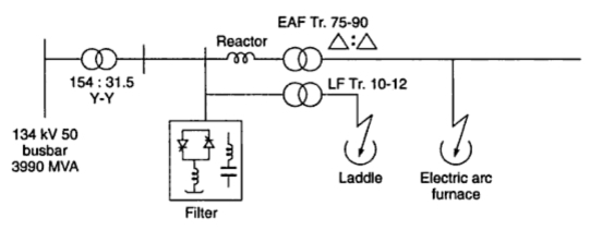
A general layout of an EAF installation is given in Fig. 1.
 |
| Fig. 1 A general schematic layout of an electrical arc furnace installation |
On the application of high voltage across an air gap, the air in
the gap gets ionized under the influence of electrostatics forces and
becomes conducting medium. Current flows in the form of a continuous
spark, called the arc. When electrodes are made of carbon/graphite, the
temperature obtained is in the range of 3000 C-3500 C. The high voltage
required for striking an arc can be obtained by using a step-up
transformer fed from a variable A.C. supply.
an arc can also be obtained by using low voltage across two
electrodes initially in contact with each other. The low voltage
required for this purpose can be obtained by using a step-down
transformer. Initially, the low voltage is applied, when the two
electrodes are in contact with each other. Further, when the two
electrodes are gradually separated from each other, an arc is
established between the two.
Arc furnaces utilise the heating effect of an electric arc to
melt the contents of the furnace. They are characterised by very high
currents, perhaps up to 200 kA, at relatively modest voltages, between,
say, about 200 and 1000 V. Because of the power required by the furnace,
which might be between 10 and 100 MVA and occasionally even up to 200
MVA or higher, and the nature of the load, the transformers will need to
take their supply from a strong HV system. In the UK it has been found
appropriate to provide a supply to furnaces of up to around 120 MVA at
33 or 66 kV derived from a supply which is usually dedicated solely to
supplying a number of arc furnaces and having a direct connection to a
grid bulk supply point so that the disturbances created on the network
will be maintained at an acceptable level. For furnaces rated at 60 MVA
and above the bulk supply point needs to be associated at least with the
275 kV system. The relatively modest 33 or 66 kV HV voltage for the
furnace transformer has the benefi t of making the insulation level of
the HV windings and the tapchangers considerably lower and therefore
less expensive than they might otherwise have been..
Operation of a Furnace Transformer
It is desirable not to switch on and off a furnace transformer
too, often and particularly during a run. The output voltages of a
Furnace transformers range between 600 V and 900 V. A number of taps are
provided on the primary side. The variations of these taps helps to
maintain a steady high voltage across the electrodes during a run. A
steady high voltage is associated with a large arc length and a lower
anode consumption. The three graphic anodes are arranged in a mechanical
delta with well-maintained distances. This helps in maintaining a
balance between the phase voltages. It also helps in reducing the
production of harmonics.
Equivalent Circuit of 3-phase Arc Furnace Transformer
3-phase Arc Furnace Transformer includes an extended primary
winding with taps there in for the secondary voltage range
235-220-205-190-175-160 V, with primary winding connected in delta. This
voltage range is extended by changing the connections of the primary
windings from delta to star giving 58 percent voltage from each tap.
Fig. 2 shows the equivalent circuit of an arc furnace.
 |
| Fig. 2 Equivalent circuit of an arc furnace |
RT = Equivalent resistance of the furnace transformer (referred to secondary side)
XT = Equivalent reactance of the furnace transformer (referred to secondary side)
RL = Resistance of the load,
XL = Reactance of the load
RE = Resistance of the electrodes,
RA = Arc resistance, and
EA = (= IRA) = voltage drop across the arc.
In order to exercise complete control of furnace temperature and
to achieve best-operating conditions both voltage and electrodes
controls are employed (The power input can be varied by raising or
lowering the electrodes, resulting in variation of RA and by changing the transformer tapping, resulting in variation of voltage across the furnace).
Conditions for Maximum output :
Power loss will be maximum when denominator is minimum
i.e., Power loss will be maximum when the arc resistance RA will be numerically equal to the impedance of the whole electrical circuit referred to the secondary excluding arc resistance RA.
''Power factor'' at maximum power loss,
However, it not economical to operate an arc furnace with primary side power factor 0.8 lagging.
Fig. 3 shows the performance characteristics of a typical arc furnce.
 |
| Fig. 3 Performance characteristics of a typical arc furnace |
. Initially when the
electrodes are short-circuited, it is as good as short-circuiting the
secondary of a transformer. The total input to the furnace is almost
zero (copper losses in the transformer winding).
. when the electrodes are far apart arc is extinguished and there is no power drawn from supply.
In between the above limits there is a particular loading when the power input to the furnace is maximum.


great blog..
ReplyDeletefurnace repair services
As one of the trusted Industrial Gas Burner Suppliers India, Axis Thermal Furnace provides high-quality burners that meet demanding industrial requirements. Our burners ensure efficient fuel usage, uniform heating, and robust performance. With a wide supply network, we support manufacturing units, process industries, and thermal applications across the country.
ReplyDelete