In addition to primary and secondary windings, the transformers
may be constructed with the third winding. This winding is called
tertiary winding. The normal two winding transformer can be converted
into three winding transformer with an additional secondary winding
having number of turns as per the requirements.
There are many reasons for which three winding transformers is employed. Some of the reasons are listed below.
1. If a two winding transformer has to supply an additional load which
has to be insulated from the secondary windings for some reasons then
three winding transformer may used with additional load carried by
tertiary winding.
2. The phase compensating devices can be supplied with three winding
transformer which are not operating at either primary or secondary
voltage but at some different voltage.
3. The tertiary winding can be used as a voltage coil in a testing transformer.4. Three supply systems operating at different voltages can be interconnected using three winding transformer.
5. The three winding transformer can be used to load large split winding generators.
6. The substation requirements can be met using three winding
transformer which requires a voltage different from that of primary and
secondary windings.
7. The tertiary winding connected in delta reduces the impedance offered
to the zero sequence currents so a larger earth fault current flows for
proper operation of protective equipment. For unbalanced load it limits
the imbalance in voltage. It permits the flow of third harmonic current
to reduce third harmonic voltage.
The third winding known as tertiary winding is generally
connected in delta. Thus when any fault or short circuit occurs on the
primary or secondary sides, there will be large unbalance of phase
voltage which is compressed by large tertiary winding circulating
current. The reactance of the tertiary winding must be such as to limit
the circulating current to that which can be carried by copper in order
to avoid overheating of tertiary winding under fault conditions.
1.3 Stabilizing Due to Tertiary Winding
For unbalanced single phase load, the star-star connection offers
high reactance to flow of current. Any unbalanced load current has
three components viz positive, negative and zero sequence components.
The zero sequence component on the secondary side can not be balanced by
primary currents as zero sequence currents can not flow in the isolated
neutral of star connected primary. On the secondary side the zero
sequence current sets up magnetic flux in the core. The iron path is
available for this flux and the impedance offered to the zero sequence
currents is very high. But the delta connected tertiary winding permits
circulation of zero sequence currents in it. So impedance offered to the
flow of zero sequence currents is lowered. For this purpose the
tertiary winding is called stabilizing winding. This is shown in the
Fig. 1.
 |
| Fig. 1 |
1.4 Equivalent Circuit of 3 Winding Transformer
While drawing the equivalent circuit of a three winding
transformer, each of the winding is represented by its equivalent
resistance and reactance. The exciting current is neglected this is
shown in the Fig. 2.
 |
| Fig. 2 Single phase equivalent circuit of three winding transformer |
All the parameters values are reduced to a common rating base and
respective voltage bases. The primary, secondary and tertiary windings
are respectively indicated by subscripts 1, 2 and 3. The circuit is
simplified by neglecting the exciting current.
The division of load between the secondary and tertiary winding
is arbitrary. External circuits are respectively connected between
terminals 1, 2, 3 and the common terminal.
As exciting current is neglected,Ī1 + Ī2+ Ī3 = 0
The determination of impedance in the above equivalent circuit is carried put from three simple short circuit tests.

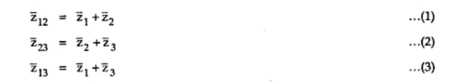
Subtracting equations (2) and (3)

Subtracting equations (4) and (1)
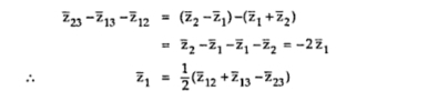
Similarly,

The open circuit test can be performed on any one of the three
windings. This helps in obtaining the core loss, magnetizing impedance
and turns ratio.
1.5 Advantages and Disadvantages of Three Winding Transformer
The advantages of a three winding transformer are as given belowi) It can supply additional load providing insulation from secondary windings.
ii) It can act as a source of voltage at substation to meet the internal
load demand of substation which is at different voltage that either of
primary or secondary voltage level.
iii) The reactive power injection into the system is possible for
voltage control by connecting synchronous condensers or static
capacitors to the tertiary winding.
iv) A delta connected tertiary winding offers less impedance to the flow
of zero sequence currents. The allows larger earth fault current to
flow through protective device facilitating its proper operation.
v) It reduces voltage unbalance under unbalanced loading conditions and
permits third harmonic current to flow which reduces third harmonic
voltages.
vi) Three transmission lines at different voltage levels can be interconnected by using three winding transformer.
vii) The third winding of a three winding transformer, usually called
tertiary winding can be used to serve purpose of measuring voltage of HV
testing transformer.
The disadvantage of a three winding transformer is its
construction is little complicated as compared to normal two winding
transformer. A separate third winding is required to be placed which
requires more copper and hence cost of three winding transformer is
obviously more. The core of the transformer has to carry three windings
instead of two as in case of normal two winding transformer.


Very useful information you shared with us. keep posting.
ReplyDeleteInductor Coil Manufacturer in India | Medical Isolation Transformer in India