Types of Magnetic Cores
The magnetic core for this type of transformer is usually an EI
or EE type using either audio-grade silicon steel or nickel-alloy tape
cores in toroidal form are used for extreme bandwidths. High
permeability ferrite cores with highly polished mating surfaces are also
used to obtain wide bandwidths.
If there is no direct current in the windings, it is possible to
design a small, high quality audio transformer with a high permeability
ferrite core. Material with initial permeability above 10 000 is
available. To minimize the air gap in the assembled core, the mating
surfaces are ground flat and polished to a mirror finish. Because of the
small core volume, when these transformers are used at low frequencies
care must be taken to avoid core saturation. The maximum flux density in
a core is given by:
Bmax = (3.49 x 10⁶) E/fNAc
where,
Bmax = maximum flux density (gauss),
E = rms volts,
f = frequency (hertz),
N = number of winding turns,
Ac = cross section of core (square inches)
Design of Audio-Frequency Transformers
Important parameters - Important parameters are generator and load impedances, Rs and Rl,
respectively; generator voltage ; frequency band to be transmitted;
harmonic distortion; and operating voltages (for adequate insulation).
Midband Frequencies - The relative low- and high-frequency responses are taken with reference to midband frequencies where
α Eout/Eg = [( 1 + Rs/Rl) + Rl/a2 Rl]-1
α Eout/Eg = [( 1 + Rs/Rl) + Rl/a2 Rl]-1
Low Frequencies - At low frequencies, the equivalent unity-ratio network of a transformer becomes approximately as shown in Fig. 1.
 |
| Fig.1 Equivalent network of an audio frequency transformer at low frequencies |
Amplitude = [( 1 + (R'par/Xm)2 ]-1/2
Phase angle = tan-1 (R'par/Xm)
where,
R'par = (R1 R2 a2 ) / (R1 + R2 a2 )
R1 = Rg + Rp
R2 = Rl + Rs
Xm = 2πfLp
In a good output transformer, Rp , Rs and Rc may be neglected. In input or interstage transformers, Rc may be omitted.
High Frequencies - At high frequencies, neglecting the effect of
winding and other capacitances, the equivalent unity-ratio network
becomes approximately as in Fig. 2.
 |
| Fig. 2 Equivalent network of an audio frequency transformer at high frequencies, neglecting the effect of the winding shunt capacitances |
Amplitude = [1 + (Xl/R'se)]-1/2
Phase angle = tan-1 (Xl/R'se)
where,
R'se = R1 + R2 a2 ,
Xl = 2 πf l scp ,
l scp = inductance measured across primary with secondary short-circuited = l p + a2l s.
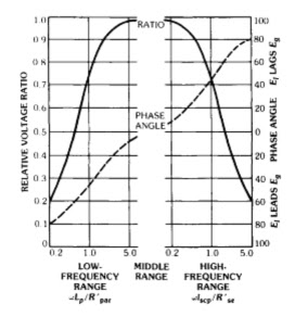
The low- and high-frequency responses are shown by the curves of Fig. 3.
 |
| Fig. 3 Universal frequency and phase response characteristics of output transformers. |
If at high frequencies the effect of winding and other
capacitances is appreciable, the equivalent network on a 1:1 turns-ratio
basis becomes as shown in Fig. 4.
In a step-up transformer, C2 = equivalent shunt capacitances of both windings. In a step-down transformer, C2 shunts both leakage inductances and R2. The relative high-frequency response of this network is given by
 |
| Fig. 4 Equivalent network of a 1:1 turns ratio audio frequency transformer at high frequencies when effect of winding shunt capacitances is apprecaible |
In a step-up transformer, C2 = equivalent shunt capacitances of both windings. In a step-down transformer, C2 shunts both leakage inductances and R2. The relative high-frequency response of this network is given by
This high-frequency response is plotted in Fig. 5 for R2 = R1 (matched impedances), based on simplified equivalent networks as indicated. At frequency fr Xl = Xc and B = Xc/Rl.
 |
| Fig. 5 Transformer characteristics at high frequencies for matched impedances |
Harmonic Distortion - Harmonic distortion requirements may a
constitute a deciding factor in the design of transformers. Such
distortion is causffed by either variations in load impedance or non
linearity of magnetizing current. The percent harmonic voltage appearing
in the output of a loaded transformer is given by
(Percent harmonics = 100Eh/Ef = 100Ih /If ( R'par/Xm) [ 1 - (R'par/4Xm) ]
where 100Ih/If = percent of harmonic
current measured with a zero-impedance source (values in table 1 are for
a 4-percent silicon-steel core).
 |
| Table 1 Harmonics by various flux densities Bm in a 4-percent silicon-steel-core audio trasformer |
Insertion Loss - Insertion loss is the loss introduced into the
circuit by addition of the transformer. At midband, the loss is caused
by winding resistance and core loss. Frequency discrimination adds to
this at low and high frequencies. Insertion loss is input divided by
output expressed in decibels, or (in terms of measured voltages and
imepdance)
(dB insertion loss) = 10 log [ (Eg2 R1) / (4Eo2 Rg ) ]
Impedance Match - For maximum power transfer, the reflected load
impedance should equal the generator impedance. Winding resistance
should be included in the is calculation: For matching
Rg = a2 ( R1 + Rs) + RpAlso, in a properly matched transformer
Rg = a2 R1 = (Zoc x Zsc)1/2
where,Zoc = transformer primary open-circuit impedance,
Zsc = transformer primary impedance with secondary winding short-circuited.
If more than one secondary is used, the turns ratio to match
impedances properly depends on the power delivered from each winding.
Ns/Np = [ (Ra/Rg) (Wa/Wp) ]1/2 Example : Using Fig. 6
N2/Np = [(10/600)(10/16)]1/2 = 0.102
N3/Np = [(50/600)(5/16)]1/2 = 0.161
N4/Np = [ (100/600)(1/16)]1/2 = 0.102
 |
| Fig. 6 Multisecodary audio trasformer |


No comments:
Post a Comment