Pulse transformers are small in size and have comparatively few
turns. Hence the leakage inductance of the windings is minimum. These
transformers have low interwinding capacitance. The cores are
constructed of ferrites or wound strips of high permeability alloys such
as permalloy. Due to this, pulse transformers have high magnetizing
inductance. The transformers have high-voltage insulation between
windings and to ground. The signal handled by the pulse transformers is
usually a pulse or train of pulse and not a sinusoidal signals as in the
case of conventional transformers. The rectangular input pulses to such
transformers is shown in the Fig. 1.
 |
| Fig. 1 Ideal rectangular pulse input (voltage or current) |
The performance of the impulse transformers is specified in terms
of its effect on the shape of the pulse input current or voltage. Small
pulse transformers used in computers, pulse generator etc. can deliver
only a few volts at pulse duration of a few hundred nanoseconds. Large
pulse transformers used in radar systems etc. can deliver power in the
range of 50-100 MW at 200-300 kV with pulse duration of a few
microseconds.
1.1 Pulse Response Characteristics
It is important that the transformer reproduce the input pulse as
accurately as possible, at its secondary terminals. there should be
minimum shape distortion while transferring the pulse from the pulse
generating circuit to the load.
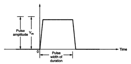
The ideal input rectangular pulse can not be obtained in
practice. This is because dI/dt can not be infinite. The practical pulse
input signal is shown in the Fig. 2.
 |
| Fig. 2 Practical rectangular input pulse |
The pulse width varied from fraction of microsecond to about 25
μsec, as mentioned earlier. The effect of pulse transformer while
transferring such a pulse to the secondary or load is analysed by
solving the differential equivalent circuit of a transformer including
stray capacitance.
Due to the stray capacitance, the output response is generally of
the type of demand oscillations. The rise time of such output response
sets the limit on the maximum pulse repetition rate, which can be
handled by the pulse transformer. The rise time adds an error distorting
the output response. Hence rise time should be kept as small as
possible. The leakage inductance is kept to a minimum value, to obtain
shortest rise time. In the pulse transformers which drives SCR's and
switching transistors, a higher rise time can increased their junction
temperatures to a limit where the devices can get damaged. Apart from
the overshoot, there is a back swing present in the response, which is
the portion of the response which extends below zero amplitude, after
the pulse width. This part of the response is called trailing edge
response. The response, till it settles down after the overshoot is
called leading edge response. While the response in between trailing
edge and the leading edge is generally flat called top response.
Hence the pulse response characteristics can be mainly divided into three sections :i) Leading edge response giving rise time characrteristics
ii) Flat top response
iii) Trailing edge response giving fall time characteristics.
The overall voltage (or current) pulse shape of pulse transformer output is shown in the Fig. 3.
In addition to the input-output impedances, turns ratio, pulse
duration and repetitions rates etc, the pulse transformer specifications
include the various parameters related to output response shown in the
Fig. 3.
 |
| Fig. 3 Distorted pulse shape of pulse transformer output |
a) Pulse amplitude :
It is the maximum absolute peak value of the pulse excluding the unwanted spikes.
b) Rise time (Tr) :
It is time taken by the output pulse to rise from 10% of peak
pulse amplitude to 90% of peak pulse amplitude, during its first
attempt. Sometimes it may be defined as the time taken by the output
pulse response to rise from 0 to pulse amplitude, for the first time.
c) Over shoot :The amount by which the output pulse exceeds its peak amplitude is called overshoot.
d) Pulse width :
The time interval between the first and last instants art which
the instantaneous amplitude reaches 50% of the peak amplitude. This is
also called pulse duration.
e) Droop :It is the displacement of the pulse amplitude during its flat response. It is also called tilt.
f) Fall time (Tf) :
It is the time taken by the output pulse to decrease from 90% of
its peak amplitude to 10% of its peak amplitude, during trailing edge
response. It is also called decay time.
g) Backswing :The portion of the trailing edge which extends below the zero amplitude level, is called back swing.
1.2 Applications of Pulse Transformers
The pulse transformers are commonly used in pulse generating
circuits, SCR and switching transistors, control circuit for controlling
the firing, radar systems cathode ray tube circuits, microwave tube
circuits, data handling circuits, analog switching applications etc. The
transmission line pulse transformers are useful in fast pulse signal
transmission applications etc. The transmission line pulse transformers
are useful in fast pulse signal transmission applications. They are also
used in digital signal transmission.


I Really want to Thank you For sharing these knowledge. it always be confusing while doing wiring before but now i know these through your blog. Thank you for Sharing these.
ReplyDeleteelectrician
Very informative blog you shared with us. keep sharing such information.
ReplyDeleteAerospace wiring harness manufacturer in India | Toroidal chokes manufacturers in India
A handyman can handle minor maintenance jobs that licensed professionals such as an electrician, plumber, or carpenter can perform, but normally at half the cost.carpenter point cook
ReplyDelete